More Information
Submitted: October 19, 2020 | Approved: April 06, 2021 | Published: April 07, 2021
How to cite this article: Samanta A, Mukherjee K, Jana PC. Tunable induced transparency and Fano-resonance in double cavity optomechanical system. Int J Phys Res Appl. 2021; 4: 019-025.
DOI: 10.29328/journal.ijpra.1001036
Copyright License: © 2021 Samanta A, et al. This is an open access article distributed under the Creative Commons Attribution License, which peRmits unrestricted use, distribution, and reproduction in any medium, provided the original work is properly cited.
Keywords: Transparency; Fano-Resonance; Optical switches
Tunable induced transparency and Fano-resonance in double cavity optomechanical system
Anjan Samanta1,2*, Kousik Mukherjee2,3 and Paresh Chandra Jana2
1Sabang Sajanikanta Mahavidyalaya, Lutunia, Paschim Medinipur, 721166, India
2Vidyasagar University, Medinipur, Paschim Medinipur, 71102, India
3Government General Degree College, Gopiballavpur-II 721517, India
*Address for Correspondence: Anjan Samanta, Sabang Sajanikanta Mahavidyalaya, Lutunia, Paschim Medinipur, 721166, India, Email: anjan.samanta744@gmail.com
We analyze optomechanically induced Transparency and asymmetric Fano-line shape Profile in a two-mode cavity system, coupling at weak and strong coupling regimes. The model system consists of one mechanical mode and two optical modes. The transmission shows nonreciprocal behavior. Both the forward transmission and backward reflection for the system are analyzed for both optic-optic and mechanical-optic cavities by considering various system parameters. The output spectra lead to sharp asymmetric Fano-resonance and tunable transparency. Double line-shape profile is observed in the output Spectrum. Our proposal provides a new platform for application in quantum telecommunications and a photonic device like optical Switches.
Induced transparency with detuning parameters for opti-cal systems has the impact to be used for potential applications such as power switching, quantum computing, etc. Different types of induced transparency are electromagnetically, optomechanically, optically, coupled mode induced trans-parency, etc. In this regard, we have discussed the tunable line-shaped fano profile in a double cavity optomechanical system.
In cavity optomechanics, the investigation of Controlled induced transparency and Fano-resonance clearly describe the controlled behavior of Electromagnetically induced transparency(EIT) for a hybrid Bose-Einstein condensate(BEC) and significantly uses in quantum, engineering [1].
Electromagnetically induced transparency a phenomenon of direct development of quantum systems exclusively observed [2,3] and finds tremendous application [4,5]. Tunable asymmetric Fano property and optically induced transparency (OIT) for weak field clearly show the application in telecom system [6], in double EIT phenomena with lab-application [7] switches, sensors, and selection of single-mode laser [8]. A Fano-like asymmetric resonance is induced with time [9] and shows a description of Ugo-Fano [10], nanoscale Structure [11,12]. The purpose of this type of research has many applications in ultra-slow wave propagation [13], Single-photon source [14], Photo Switch [15], Quantum wavelength conversion [16], Optical narrow cavity system like microresonator, four-wave mixing [17], Quantum Trampling [18], ultra-high-precision assessment [19,20]. Squeezing of a mechanical observation in the sideband state [21,22] can’t be solved in the traditional Opto-mechanical way.
It requires a new technique. Chen, et al. [23] build a new technique in which a slow light is realized in BEC. A tunable Fano-resonance can be achieved via the Passive - Passive regime [6]. In recent times the Fano-resonance property has been shown for double cavity configuration [24]. The induced transparency and Fano-resonance have been achieved by the study of absorption and dispersion profiles for output field probe frequency [25]. The correlation function has been calculated [26]. Controlled behavior of EIT has been shown for transverse fields [1]. Fano-resonance has also been presented in a hybrid cavity system for different parameters [27,28]. However, to the best of our knowledge multiple Fano-resonances useful in three-dimensional Plasmon ruler [29], highly directive antenna [30], Humble Waveguide [31]. EIT is a result of the Interference effect which is known as Fano interference [32,33]. Fano resonance and EIT Occurs in single silica - fiber taper [34]. In Quantum optics it has also been shown that by using a microcavity it is possible to design an optical switch and also optical sensor [36]. So to understand the quantum interference in EIT we have focused on this type of research. Our study concentrates the tunable transparency and Fano resonance for the system. We theoretically solved and plot via different experimental data which is published [6].
In this paper ‘Fano-resonance and tunable transparency in double cavity Opto-mechanical system’, has been investigated as ref. 6. We represent a model: Hamiltonian with double cavity coupled mechanically which is controlled by a control field and probe field. The system is illuminated by a laser field. In this paper, we present the solution for the proposed Hamiltonian and have discussed dynamically the Heisenberg-Langevin equations for input-output theory. We have shown forward and backward reflection rates by varying different system parameters. We present here the induced tunable transparency and asymmetric Fano-resonance for two different situations, one for coupling parameter and detuning term. For their application in Quantum Opto-mechanics.
Theoretical calculation
The model consists of one mechanical mode (b) and two optical modes (a and c). They are coupled within the cavities by mechanical mode via optomechanical interaction. The cavity is externally driven by a laser field which is expressed by
The Hamiltonian of the system can be written as (ħ = 1)
(1)
Here ∆j = ωj - ωl (j = 1,2) is the corresponding cavity laser detuning. ωj & ωm are resonance Frequencies of the corresponding optical cavity and mechanical resonator. ∆1 is the frequency detuning ∆2 is the probe frequency detuning.
Here a(α✝), b(b✝), c(c✝) are annihilation (creation) operators for the cavity field modes.
In the Hamiltonian, the first & second part describes the fundamental and second harmonic optical field mode with frequency ωa & ωc and the third term represents mechanical mode, with frequency ωb. Here λ represents tunneling strength, which interacts between two modes with a photon. Now the nonlinear term of the system represents by g. The last two parts are the intense control and weakened probe field. The field strengths are related to the control field power by the relation
P = Laser power. kj= corresponding cavity decay rate. The classical laser field is applied to the ordinary cavity, we can’t use it for the optomechanical cavity [38]. Here we use three situations of coupling coefficients µ, it defines three situations µ < 1/2, µ = 1/2, µ > 1/2. It is referred to as under coupling, critical coupling, and over coupling.
Calculation of dynamics
In the mechanical displacement at a frequency ωm for the input control field, the total Hamiltonian is transformed by , the nonlinear coupling can be Diagonalized as under week Optomechanical coupling 1 and the transformed Hamiltonian can be written as
(2)
Where Kerr type nonlinear strength induced by optomechanical coupling.
Considering the effect of quantum noise term the Heisenberg-Langevin equations for the field modes are written as
The perturbation operators satisfy the following correlations
(4)
Where the equation [3] satisfies the following equation.
For this purpose, we use the following parameters
To examine the expectation values of small quantum fluctuations of the above equation we use the matrix formation to calculate the fluctuations components of Optic and mechanical field’s modes for solving the Eigenvalue equation. We obtain the fluctuation parameters which help us to calculate the forward and backward reflection profile.
(6)
After matrix transformations, we get
(7)
B+ = 0
(8)
For this calculation, we have used the constants
For a laser field, the input-output information is
(9)
Here α β represents the input, output signal information respectively.
Applying standard input-output theory for this model
(10)
So in equation (10) both the input and output fields have their frequency components. The first two indicate input and output field frequency and the third one is for additional frequency component 2ωc - ωp called stokes field frequency [37]. To study forward power transmission and backward power reflection we are interested in the component of output field frequency.
For the probe field frequency, the ratio of output to input field amplitude for forward transmission and backward reflection is given by
The forward transmission rate and backward reflection rate of the probe, field are derived as
(11)
(12)
Where w =
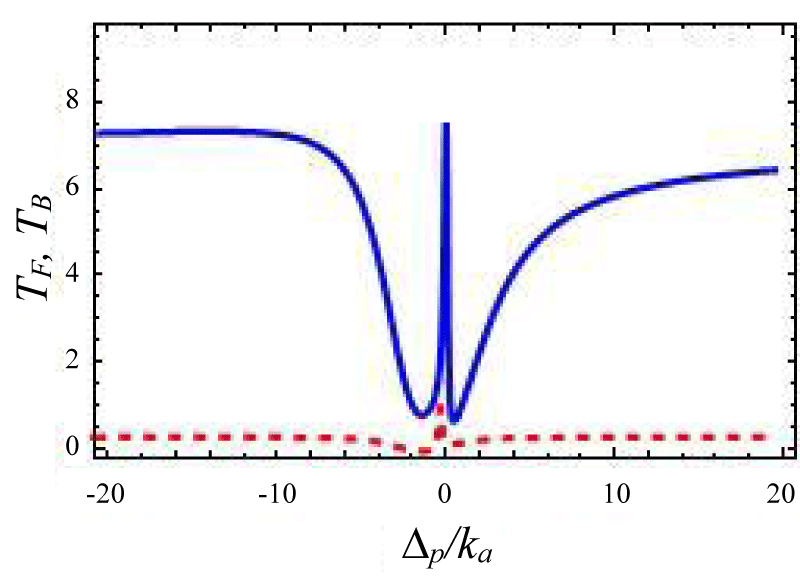
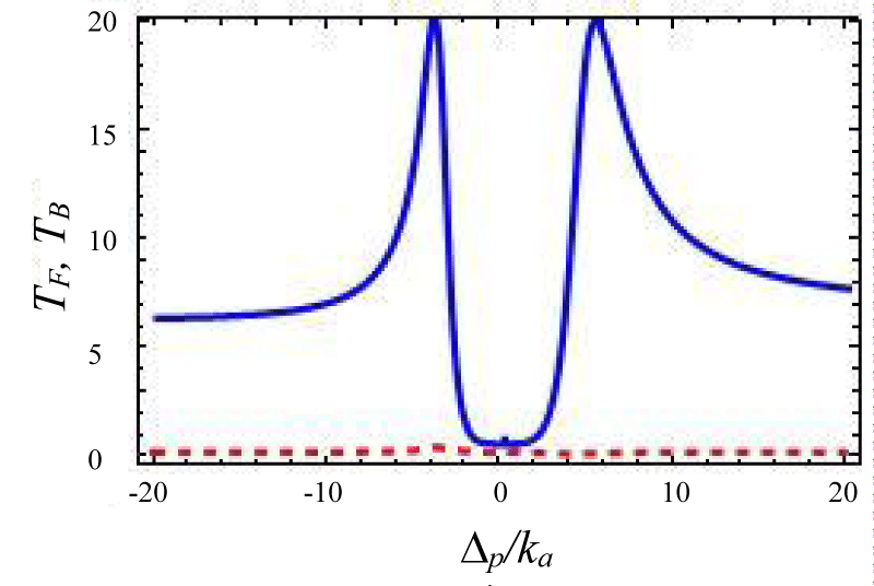
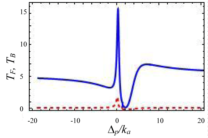
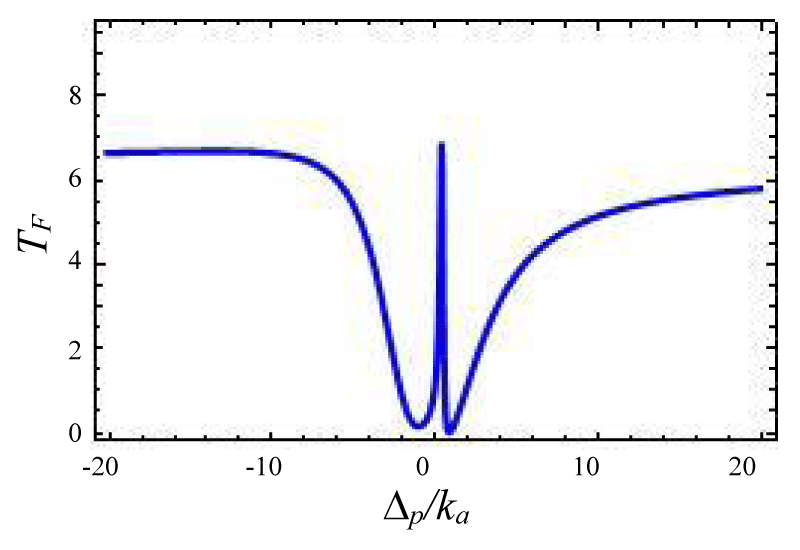
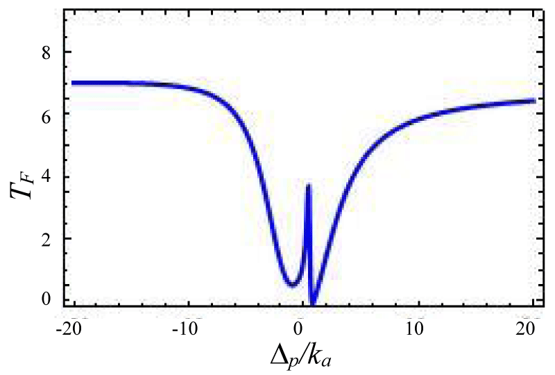
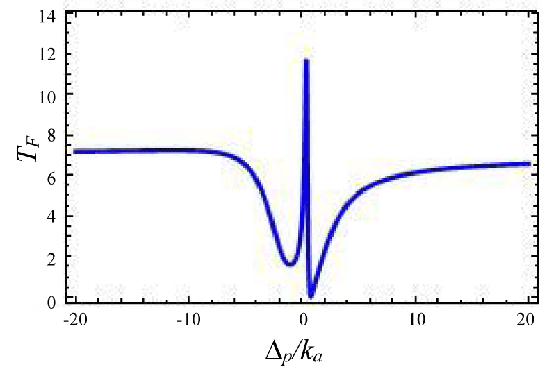
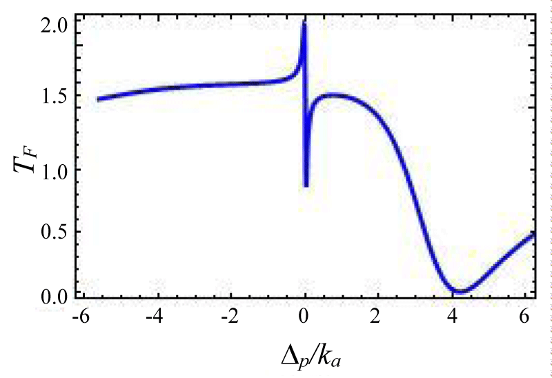
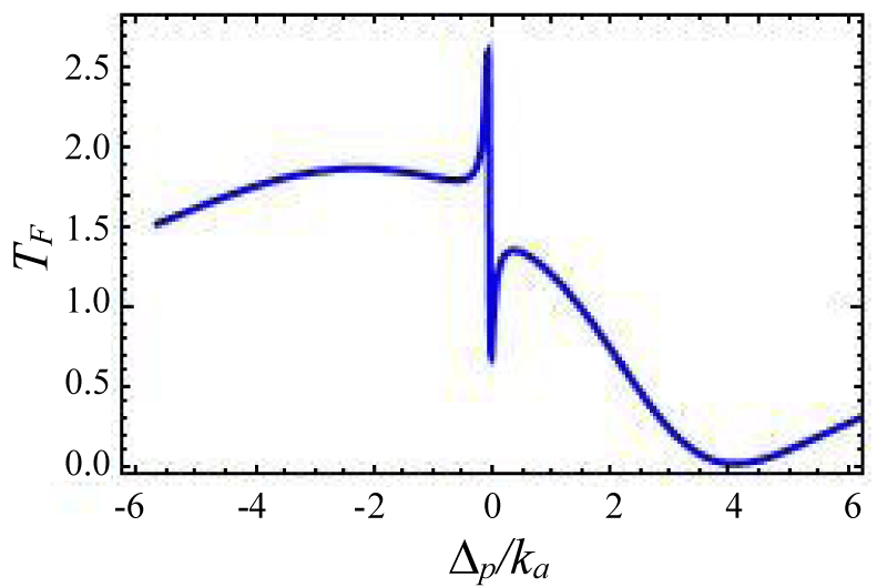
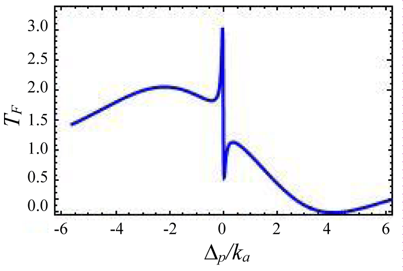
In this section, we have discussed the transmission of the probe field with respect to system parameters. We present different situations by using forward and backward reflection rates as a function of normalized probe detuning and different field parameters. The tunable external laser having 1350 nm band is used as control or pump laser and other with 1450 nm band is used as probe laser. A cavity resonator can be designed from silica. This setup can emit photons in the wavelength band 1500 nm band for a laser driving wavelength 900 nm or 1350 nm bands. By slit change of the resonator gap the total loss rate can be tuned via external coupling loss rate. The effective gain rate in the cavity is ≈ -2π × 10.5 MHz. The photon tunneling rate between the two cavities is ≈ -2π × 5.5 MHz, and it can be timbre by changing the gap between the cavities. The optical kerr medium strength ≈ -2π × 1.05 MHz. The gain to loss ratio for this cavity system varies from -3 to +3 [40-46]. We propose the transmission and reflection profiles over critical region . Figures 2-4 represent photon tunneling strength on the forward transmission and backward reflection rate for the double cavity mechanical system. It is seen from figure 2 that forward transmission rate TF has a single transparent peak around ∆p/ka = 0 and two dips are there on both sides of it. So it represents symmetric dip peak –dips spectral structure and confirms the IT effect. In figure 3 if we increase the cavity coupling strength λ = 0.4, and the two dips around 2 appear and the width of the transparency increases. Hence one may tune the IT by increasing detuning parameter and coupling strength (here reflection rate is very small due to the small gain to the loss ratio). If we choose coupling strength 1.67 (Figure 3) the reflection profile splits into two peaks and expiates the forward rate and the separation between two peaks depends on the tunneling strength and weak coupling parameters. Next, we have studied the variation of forward transmission rate with strength.
Figure 1:
Figure 2:
Figure 3:
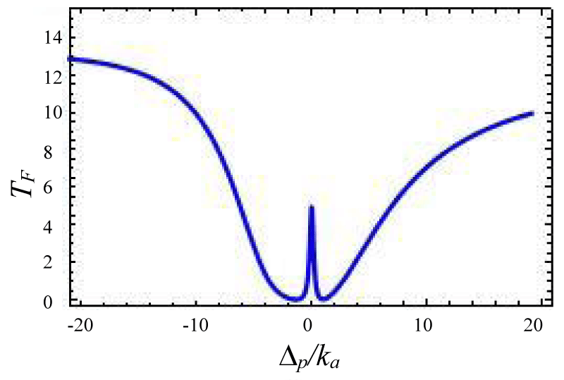
Figure 4:
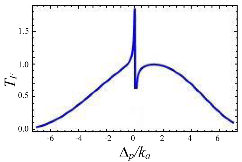
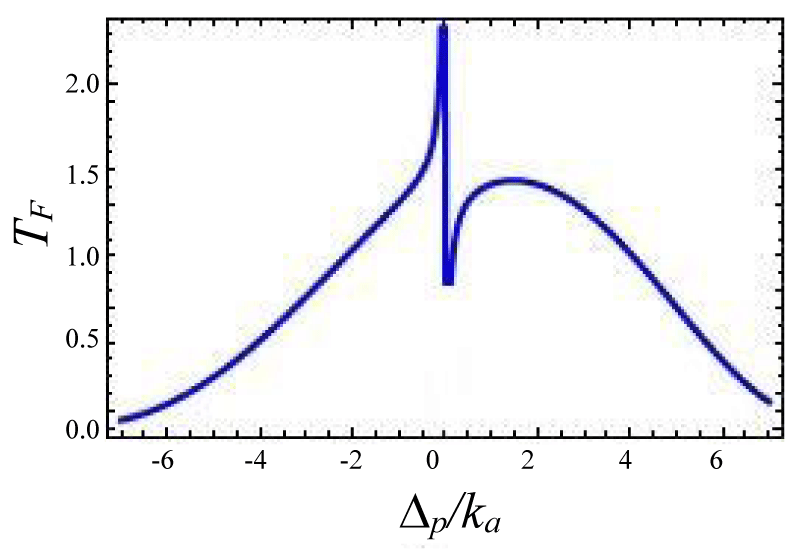
Figures 4-7 show the variation of forward transmission rate with probe strength for the Optic-Optic system. Now we have plotted line shape transmission spectra for a double Optomechanical system. In figure 5 we have taken Optic cavity detuning ∆a = - 0.01ka; the plot of TF has a sharp peak around the center i.e. ∆p = 0 and two symmetric dips around both sides of the peak. In figure-6 all the parameters remain the same as in figure 5 except the passive cavity detuning ∆a = - 0.02ka. There is an increase in transparency peak and the dips nature are asymmetric. It is also called a two-sided coupled cavity system. The frequency of this line always is close to the cavity mode which indicates the origin of the Fano [39]. For the same cavity detuning if we decrease the value of effective gain kc = - 1.0ka then the peak height also reduces as shown in figure 7. At kc = - 2.0ka with all other parameters remain unchanged the transparency peak disappears. So the transmission rate is controlled by changing the gain to lose ratio. In figure 8 if we use λ = 0.067 then the profile is highly asymmetric. This profile shows an asymmetric Fano line Shape.
Figure 5:
Figure 6:
Figure 7:
Figures 4-7 Plot of forward transmission rates (blue line) for normalized probe
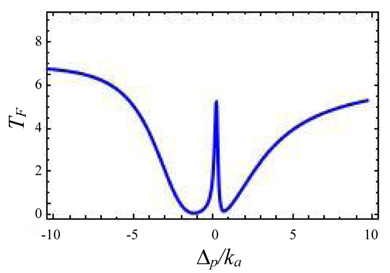
Now we calculate the forward transmission and backward reflection in the over- coupling region by taking µ = 2. The interference between two optical systems excited simultaneously in a resonator creates EIT otherwise Fano-resonance. The several transmission line shape is manipulated by γj + ωj Σ(j = 1, 2) with between two optical cavities which affect the transmission reflection profile. In our calculation, both the cavity photon and incident laser source have the same polarization. When Σ >> γj + ωj i.e no interaction between these cavities then there are two separate dips in transmission spectrum but if Σ < γj + ωj then two modes interact, and the Fano line shape is formed. If Σ (Kerr-type nonlinear strength) is decreased further i. e. the interaction between two optic modes is stronger than the Fano lineshape has more contrast as shown in figures 8-11 and when it becomes zero that means Fano line Shape became EIT. It also clear from figure 12, the case zero asymmetries, which shows symmetrical resonance which is referred to as anti-resonance [39].
Figures 8-11 Plot of forward transmission rate TF (blue line) for normalized probe:
Figure 8:
Figure 9:
Figure 10:
Figure 11:
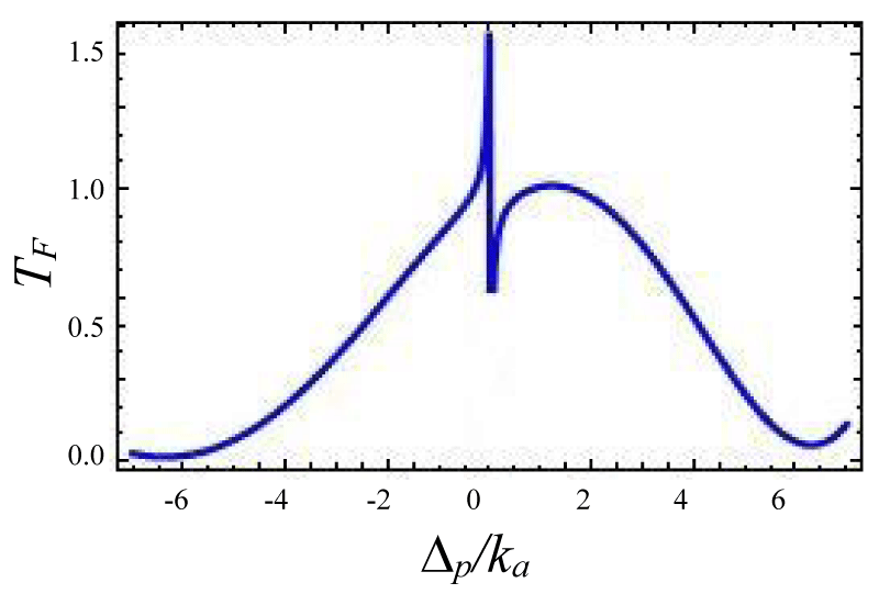
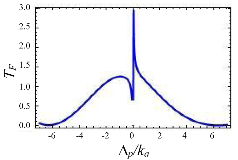
Figures 12-15 shows the variation of forward transmission rate with probe detuning in over coupling regime for Optic-mechanical System. It is to be noted that if the coupling parameters are 0.1 then there is no effect in output transmission. Figure 12 shows absorptive properties of the system if we change the coupling parameter ratio from . The Transmission line shape changes more drastically. In figures 13-15 line shape picture is generated and the result has zero probe asymmetric Fano line shape due to the presence of the coupling term ga✝a (b✝ + b) in the Hamiltonian. Figure 15 is a mirror type image of figures 15,16 where other variables remain unchanged but coupling constant changes from as is indicated by the input power of laser sources. Asymmetric nature can be tuned via gain to lose ratio as shown in figures 13,14. Figure 13 indicates a sharp Fano line with a resonance peak at ∆p = 0.00341ka and dip at ∆p = -0.00567ka, the Fano spectral width is of 0.00908ka. The forward transmission contrast with Fano resonance by approximately 60%which satisfies the minimum criterion for a telecommunication system [35].
Figures 12-15 Plot of forward transmission rate TF (blue line) constant variables:
Figure 12:
Figure 13:
Figure 14:
Figure 15:
Again if we decrease the non linear coupling parameters then the transmission profile almost remain same but its peak become sharp and increases height. From this study the Fano line shape is ruled out and transmission profile is absorptive.
In conclusion, we have investigated the tunneling effect and Fano resonance for double cavity Optomechanical system via Forward transmission and backward reflection profile. These results support how Fanoresonance is controlled in various optical systems. The results are very interesting for destructive and constructive line shape with anti-symmetric tunable Fano-resonance. we have focused here on how Fano resonance in light, propagates through the optical device and how we can use this type of research in quantum optical communications and can enrich our optical device for using line optical switches. We model this for two coupling schemes i.e for critical and over coupling. Here we have shown that both the profile continuously changes due to gain to loss ratio and coupling strength with coupling parameter. For the Optic-Optic cavity configuration, the transmission spectra show asymmetric behavior which can be controlled by an input/ output probe. In our study, we use coupling parameters opposite sign for an active-passive and the same sign for the passive-passive system. This study is useful for different optical switching systems and also telecom systems.
Author contribution statement
This worked was discussed by three authors and careful reading verified the output profile. AS performed theoretical calculations and wrote the paper.
- Kashif AY, Wu-Ming Liu. Nature. Scientific. Report, 2016; 10. 1038-22651.
- Scully MO, Zubairy MS. Quantumn Optics (Cambridge University Press). 1997; 67. 630. 43458.
- Safavi-Naeini AH, Mayer Alegre TP, Chan J, Eichenfield M, Winger M, et al, Electromagnetically induced transparency and slow light with optomechanics. Nature. 2011; 472: 69-73. PubMed: https://pubmed.ncbi.nlm.nih.gov/21412237/
- Harris SE, Field JE, Imamoglu, A, Nonlinear optical processes using electromagnetically induced transparency. Phys Rev Lett. 1990; 64: 1107-1110. PubMed: https://pubmed.ncbi.nlm.nih.gov/10041301/
- Boller KJ, Imamoglu A, Harris S. Observation of electromagnetically induced transparency. Phys Rev Lett. 1991; 66; 2593-2596. PubMed: https://pubmed.ncbi.nlm.nih.gov/10043562/
- Mukherjee K, Jana PC. Optically induced transparency in coupled micro-cavities: tunable Fano resonance. Eur Phys JD. 2019; 73: 264.
- Akram MJ, Ghafoor F, Saif F. Electromagnetically induced transparency and tunable fano resonances in hybrid optomechanics. J Phys B At Mol Opt Phys. 2015; 48: 065502.
- Lu Y, Fu X, Chu D, Wen W, Yao J. Nested microring resonator with a doubled free spectral range for sensing application. Optics communications. 2011; 284.
- Peng LF, Ozdemir B, Long SK, Yang GL. Applied Phys Letter. 2014; 105: 1101112.
- Miroshnichenko AE, Flach S, Kivshar YS. Fano resonances in nanoscale structures. Rev Mod Phys. 2010; 82: 2257.
- Yanchuk BL, Zheludev NI, Maier SA, Halas NJ, Nordlander P, et al. The Fano resonance in plasmonic nanostructures and metamaterials. Nat Mater. 2010; 9: 707-715. PubMed: https://pubmed.ncbi.nlm.nih.gov/20733610/
- Christ A, Tikhodeev SG, Gippius NA, Kuhl J, Giessen H, Waveguide-Plasmon Polaritons: Strong Coupling of Photonic and Electronic Resonances in a Metallic Photonic Crystal Slab. Phys Rev Lett. 2003; 91: 183901. PubMed: https://pubmed.ncbi.nlm.nih.gov/14611284/
- Teufel JD, Li D, Allman MS, Cicak K, Sirois AJ, et al. Circuit cavity electromechanics in the strong-coupling regime. Nature. 2011; 471: 204-208. PubMed: https://pubmed.ncbi.nlm.nih.gov/21390127/
- Agarwal GS, Huang S. Optomechanical systems as single-photon routers. Phys Rev A. 2012; 85: 021801.
- Qu K, Agarwal GS. Phonon-mediated electromagnetically induced absorption in hybrid opto-electromechanical systems. Phys Rev A. 2013; 87: 031802.
- Hill JT, Safavi-Naeini AH, Chan J, Painter O. Coherent optical wavelength conversion via cavity optomechanics. Nat Commun. 2012; 3: 1196. PubMed: https://pubmed.ncbi.nlm.nih.gov/23149741/
- Huang S, Agarwal GS. Normal-mode splitting and antibunching in Stokes and anti-Stokes processes in cavity optomechanics: Radiation-pressure-induced four-wave-mixing cavity optomechanics. Phys Rev A. 2010; 81: 033830.
- Agarwal GS, Huang S. Optomechanical systems as single-photon routers. Phys Rev A. 2012; 85: 021801.
- Zhang JQ, Li Y, Feng M, Xu Y. Precision measurement of electrical charge with optomechanically induced transparency. Phys Rev A. 2012; 86: 053806.
- Wang Q, Zhang JQ, Ma PC, Yao CM, Feng M. Tunable high-order sideband spectra generation using a photonic molecule optomechanical system. Phys Rev A. 2015; 91: 063827.
- Wang DY, Bai CH, Wang HF, Zhu AD, Zhang S. Steady-state mechanical squeezing in a double-cavity optomechanical system. Sci Rep. 2016; 6: 24421. PubMed: https://pubmed.ncbi.nlm.nih.gov/27917939/
- Dalafi A, Naderi H, Motazedifard. Effects of quadratic coupling and squeezed vacuum injection in an optomechanical cavity assisted with a Bose-Einstein condensate. Phy Rev A. 2018; 97: 043619.
- Chen B, Jiang C, Zhu KD. Manipulation of slow and superluminal light based on a graphene nanoribbon resonator. Phys Rev A. 2011; 83: 055803.
- Wallauer J, Walther M. Fano line shape and phase reversal in a split-ring resonator based metamaterial. Phys Rev B. 2013; 88: 195118.
- Qu K, Agarwal GS. Phonon-mediated electromagnetically induced absorption in hybrid opto-electromechanical systems. Phys Rev A. 2013; 87: 031802.
- Samanta A, Jana PC. Study of First & Second order Correlation Function for Two Composite State. IJERD. 2020; 16.
- Qu K, Agarwal GS. Fano resonances and their control in optomechanics. Phys Rev A. 2013; 87: 063813.
- Akram MJ, Ghafoor F, Sair F. Electromagnetically induced transparency and tunable fano resonances in hybrid optomechanics. J Phys B. 2015; 48: 065502.
- Liu N, Hentschel, Weiss T, Alivisatos AP, Giessen H. Three-dimensional plasmon rulers. Science. 2011; 332: 1407-1410. PubMed: https://pubmed.ncbi.nlm.nih.gov/21680838/
- Artar A, Yanik AA, Altug H. Multispectral Plasmon Induced Transparency in Coupled Meta-Atoms. Nano Lett. 2011; 11: 3694.
- Liu N, Mukherjee S, Bao K, Brown LV, Dorfmuller J, et al. Magnetic plasmon formation and propagation in artificial aromatic molecules. Nano Lett. 2012; 12: 364 -369. PubMed: https://pubmed.ncbi.nlm.nih.gov/22122612/
- Fano U. Effects of Configuration Interaction on Intensities and Phase Shifts. Phys Rev. 1961; 124: 1866.
- Miroshnichenko AE, Flach S, Kivshar YS. Fano resonances in nanoscale structures. Rev Mod Phys. 2010; 82: 2257-2298.
- Li BB, Xiao YF, Zou CL, Jiang XF, Liu YC, et al. Fano resonances in metallic grating coupled whispering gallery mode resonator. Appl Phys Lett. 2012; 100: 021108.
- Reed GT. Silicon optical modulators. Nat Photon. 2010; 4: 518.
- Mukherjee K, Jana PC. Tunable terahertz optical bistability and multistability in photonic metamaterial multilayers containing nonlinear dielectric slab and graphene sheet. Physics. 2020; 117: 113780.
- Hung S, Agarwal GS. Normal-mode splitting and antibunching in Stokes and anti-Stokes processes in cavity optomechanics: Radiation-pressure-induced four-wave-mixing cavity optomechanics. Phys Rev A. 2010; 81: 033830.
- Wang DY, Wu Q, Yu YF, Zhang ZM. Optical nonreciprocal response and conversion in a Tavis-Cummings coupling optomechanical system. Phys Rev A. 2019; 99: 043818.
- Miroshnichenko AE, Flach S, Kivshar YS. Fano resonances in nanoscale structures. 2003; 0902: 3014.
- Chang JH, Lin WH, Wang PC, Taur J, Ku TA, et al. Solution-processed transparent blue organic light-emitting diodes with graphene as the top cathode. Sci Rep. 2015; 5: 9693. https://www.ncbi.nlm.nih.gov/pubmed/25892370
- Vahala KJ. Optical microcavities. Nature. 2003; 424: 839-846. PubMed: https://pubmed.ncbi.nlm.nih.gov/12917698/
- Vahala KJ. Optical Microcavities in Advanced Series in Applied Physics, World Scintific. 2004; 5.
- Peng B. Parity–time-symmetric whispering-gallery microcavities. Nat Phys. 2014; 10: 394.
- Peng B, Özdemir SK, Rotter S, Yilmaz H, Liertzer M, et al. Loss-induced suppression and revival of lasing. Science. 2014; 346: 328-332. PubMed: https://pubmed.ncbi.nlm.nih.gov/25324384/
- Reed GT. Silicon optical modulators. Nat Photon. 2010; 4: 518.
- Li S, Ge Q, Wang Z, Martín JC, Yu B. Optical bistability via an external control field in all-fiber ring cavity. Sci Rep. 2017; 7: 8992. PubMed: https://pubmed.ncbi.nlm.nih.gov/28827618/
