
More Information
Submitted: September 16, 2024 | Approved: October 04, 2024 | Published: October 07, 2024
How to cite this article: Palvai GK. Comparison of Rhodium, Vanadium, Cobalt, Inconel & Silver Emitter Self-Powered Neutron Detectors: Literature Review Article. Int J Phys Res Appl. 2024; 7(2): 139-147. Available from: https://dx.doi.org/10.29328/journal.ijpra.1001099
DOI: 10.29328/journal.ijpra.1001099
Copyright License: © 2024 Palvai GK. This is an open access article distributed under the Creative Commons Attribution License, which permits unrestricted use, distribution, and reproduction in any medium, provided the original work is properly cited.

Comparison of Rhodium, Vanadium, Cobalt, Inconel & Silver Emitter Self-Powered Neutron Detectors: Literature Review Article
Girish Kumar Palvai*
Electronics Corporation of India Limited, Hyderabad, Telangana, India
*Address for Correspondence: Girish Kumar Palvai, Electronics Corporation of India Limited, Hyderabad, Telangana, India, Email: girishdet@ecil.co.in
Self-Powered Neutron Detectors (SPNDs) are in use as in-core Neutron Fluence Detectors in Nuclear Power Plants. Though the detectors are simple in design and have a common structure for the same application, there are various types of emitters (neutron-sensitive electrodes) that make SPNDs categorized into different types. There are various SPNDs in application at different types of nuclear power reactors. SPND emitters are chosen based on their characteristics/behavior in the neutron & gamma flux environment in the reactor core. A detailed Literature Review was done on five different types of SPNDs. This paper focuses on the physics behind the operation, characteristics, and review of Vanadium, Rhodium, Inconel, and Cobalt & Silver emitter-based SPNDs. A comparison study was done by a literature review on these detectors.
Large core power reactor requires Neutron flux monitoring for studying local power perturbations. These detectors are simple in design and useful for monitoring Neutron flux in the presence of high gamma fields inside the core. This is due to their relatively very low sensitivity to gamma radiation even for high-energy gamma radiation inside the reactor core.
The basic design of SPND is shown in Figure 1 [1].
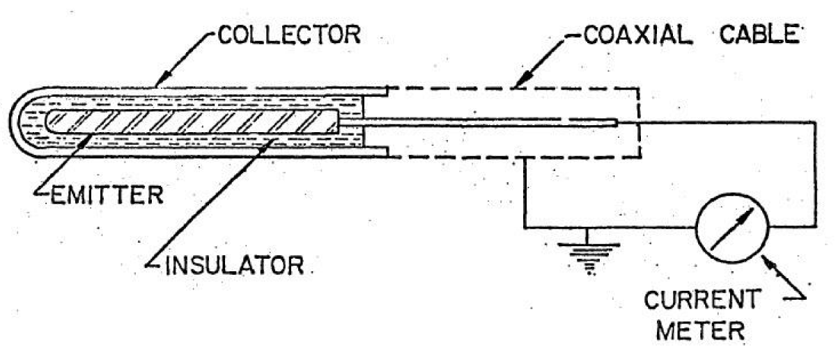
Figure 1: SPND scheme [1].
An Emitter is a Neutron-sensitive material in the detector that emits charged/ionizing radiation when a Neutron interacts with it. The gap between the Emitter (E) and Collector (C) is usually less than 1mm and no potential is required to collect the charged radiation/particles. A potential difference is created due to the transfer of this charge to the collector electrode thus leading to a current flow, between the emitter and collector, which is then processed by the electronics. The equivalent circuit of SPND is shown in Figure 2 [2].
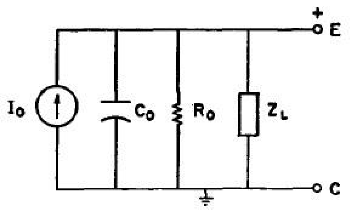
Figure 2: Electrical equivalent scheme of SPND [2].
The signal communication cable for SPND is usually a Mineral Insulated(MI) Cable with either single or double conductors. The parasitic signals generated in the emitter and core of MI cable due to the emission of Compton and Photoelectrons by the gamma environment need correction. This is achieved by providing two cores in cable. The output current is subtracted from the SPND output current employing electronics.
SPNDs are preferred for in-core neutron flux monitoring due to characteristics like no requirement of power supply, smaller dimension, reproducible linear signal, stability under temperature/pressure conditions & low burn-up [3].
These detectors are used for Reactor Control/safety and local neutron flux monitoring. Depending on the application and the conditions, different types of emitters are used in SPNDs.
Usually, many research articles have explained the operation of specific types of emitter SPNDs but no comparative information is available for the end users. This paper focuses on the comparison of the different types of emitter materials which would help naive researchers and engineers.
However, more details are yet to be reviewed for Inconel type emitter which is an alloy. Decay schemes of isotopes of different elements in the Inconel material have to be yet reviewed for sufficient literature.
Principle
The charge generation in a typical SPND is shown in Figure 3.
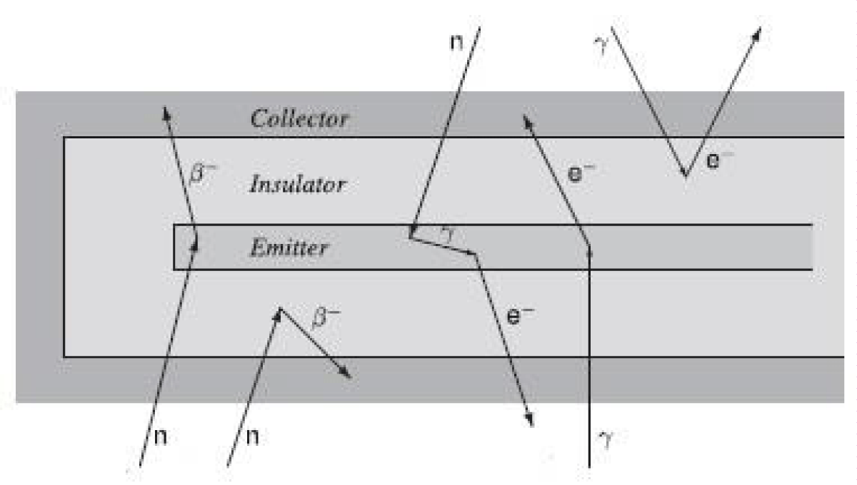
Figure 3: Charge generation interactions in SPND [4].
The electrical current flow in any SPND is due to three main interactions with incident Neutrons.
They are i) (n, β) ii) (n,γ,e) & iii) (γ, e)(n,β) interaction
“Emitter material captures neutrons and results in radioactive daughter nuclides which decay by beta particle emission. These high-energy electrons are responsible for the current flow between the emitter and collector.
(n,γ, e) interaction
Neutron capture in the emitter and collector electrode materials of the detector is normally accompanied by the emission of prompt capture γ-rays. The Emitter and Collector materials may interact with these γ-rays through Compton and Photo-electric effect resulting in the emission of high-energy electrons, leading to an electrical current flow. This interaction is referred to as the (n,γ,e) interaction. Emitters producing electrical currents through (n,γ,e) interactions dominantly are preferred for making SPNDs. The electrical current is proportional to the neutron intensity and is prompt, i.e. instantaneous change of Neutron flux will change the electrical current.
(γ, e) interaction
Gamma rays from the nuclear reactor itself, impinging on the detector, can liberate free electrons, thus producing an electrical current flow. This interaction is hereinafter referred to as the (γ,e) interaction. In a nuclear reactor, these external γ-rays result from neutron capture in the fuel and the nuclear reactor hardware, Hence the γ-ray flux, and the (γ,e)-induced electrical current, are proportional to the neutron flux. The basic detector interaction is prompt, but in a nuclear reactor, a significant fraction of the γ-rays is delayed, i.e. those γ-rays arising from the decay of fission products and activation products. Hence, the (γ,e)-induced electrical current does not follow changes in flux completely instantaneously, but has a delayed component.
The electric current from any SPND is thus given by,
(i)
This electric current is proportional to the Neutron absorption interaction rate.
The total interaction rate ‘F’ for a given detector volume ’V’ at a point ‘r’ due to neutron density ‘n’ is given by [4]
(ii)
Where,
is total neutron flux at point ‘r’ with energy e.
µ∈ is macroscopic crosssection; ∈ stands for a(absorption), s(scattering) etc.
Characteristics of a SPND
Neutron sensitivity: It is defined as the ratio of SPND net output current to the Neutron Flux seen by the sensitive part of the detector (emitter).
(iii)
Where ‘I’ is the net output current of the detector, ‘φ’ is the thermal neutron flux at the detector location.
Warren has proposed an analytical formula [5] for the calculation of current from the SPND detector given as
(iv)
Where,
‘e’ represents the elementary charge and its value is 1.6 x 10⁻¹⁹ Coulombs
‘L’ is the length of the emitter (in unit length, cm)
‘A’ is the cross-sectional area of the emitter (cm2)
‘R’ is the decay rate of the excited nucleus (cm-3)
‘εβ’ is the probability of electrons reaching the outer surface of the emitter
‘εE’ is the probability of electrons escape caused by space electric field effect in the insulator
Sensitivity could be specifically written as [6]
(v)
(vi)
Where,‘R’ is neutron capture reaction rate
‘L’ is the length of the SPND emitter
‘d’ is the diameter of the SPND emitter
‘Jec’ is net current from SPND
‘Jei’ is electron flow on the surface of the emitter
‘Jic’ is electron flow on the surface of the insulator
‘f’ is electron escape probability [refer eq(xi)]
Burn-up rate
The formation of radio nuclides results in the emission of ionizing radiation from the emitter. During this process, the nuclides reach their stable state and thus can’t interact with the incident Neutrons. This process leads to the depletion of the sensitive emitter material and is often referred to as the burn-up of material. The burn-up rate depends on the interactions with the incident neutron fluence and thus increases with the time of operation.
The time-dependent burn-up rate, b(t), of the emitter material at a given time ‘t’ is defined as [7]
(vii) [7]
Where,N(t) is time dependent atomic number density for material
σa(E) is the neutron absorption cross section for a given stable isotope.
∅(e,t) is time dependent scalax flux
The time integrated burn-rate B(t), at a given time ‘t’ is given by [7]
(viii)
Esfr → is full energy range of sodium cooled fast reactor.
Response time
The response time of any SPND depends upon the half-life of daughter nuclides responsible for major electric current generation from SPND.
(n,γ,e) the interaction produces a prompt electrical current signal while the (n.β) and (γ,e) interactions result in delayed electrical current signals. A detector, in which the (n,γ,e) interaction dominates, is preferable in many applications.
Self shielding effect
Surface atoms of the emitter see the full neutron flux compared to the atoms away from the surface. This is due to the absorption near the surface. This emitter diameter-dependent effect is called as Self Shielding Effect.
A burn-up dependant effective neutron self-shielding ratio (SSR) is defined as follows [8]:
(ix)
Where,
‘σ’ is neutron capture cross-section
‘V’ is the Volume of the emitter
‘Φ’ is Neutron flux in the emitter
‘B’ denoted a partially burned detector
‘F’ denotes fresh detector
Critical radius
The electrons released from the emitter shall reach the collector passing the insulator. The drift of electrons released from the emitter towards the collector creates a spatial electric field in the insulator. The electric field direction will reverse at a position which is called a critical radius. It is expressed as [6]
(x)
‘ri’ is the outer radius of the insulator
‘re’ is the outer radius of the emitter
Electron escape/drift probability
It is defined as the probability that an electron could reach the collector leading to an effective signal. Its analytical expression is given by [6]
(xi)
Emitters and their characteristics
There are different emitters, in use, which have “pros & cons”. The selection of a particular emitter is dependent on the end application. The well-known types are
Vanadium: Vanadium emitter comprises 0.24% 50V23 & 99.76% 51V23. The 50V23 converts to 51V23 when it interacts with the neutron. The cross-section is 100 barns. The current from Vanadium SPND is due to (n,β) interaction for 51V23 with a thermal neutron cross-section of ~5 barns.
The interaction scheme of vanadium-51 is as shown in Figure 4 [9].
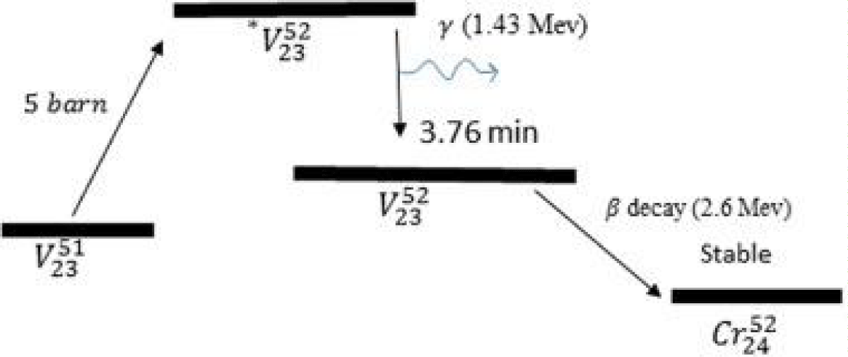
Figure 4: Interaction scheme of Vanadium-51 [9].
The cross-section vs. neutron energy plot is shown in Figure 5.
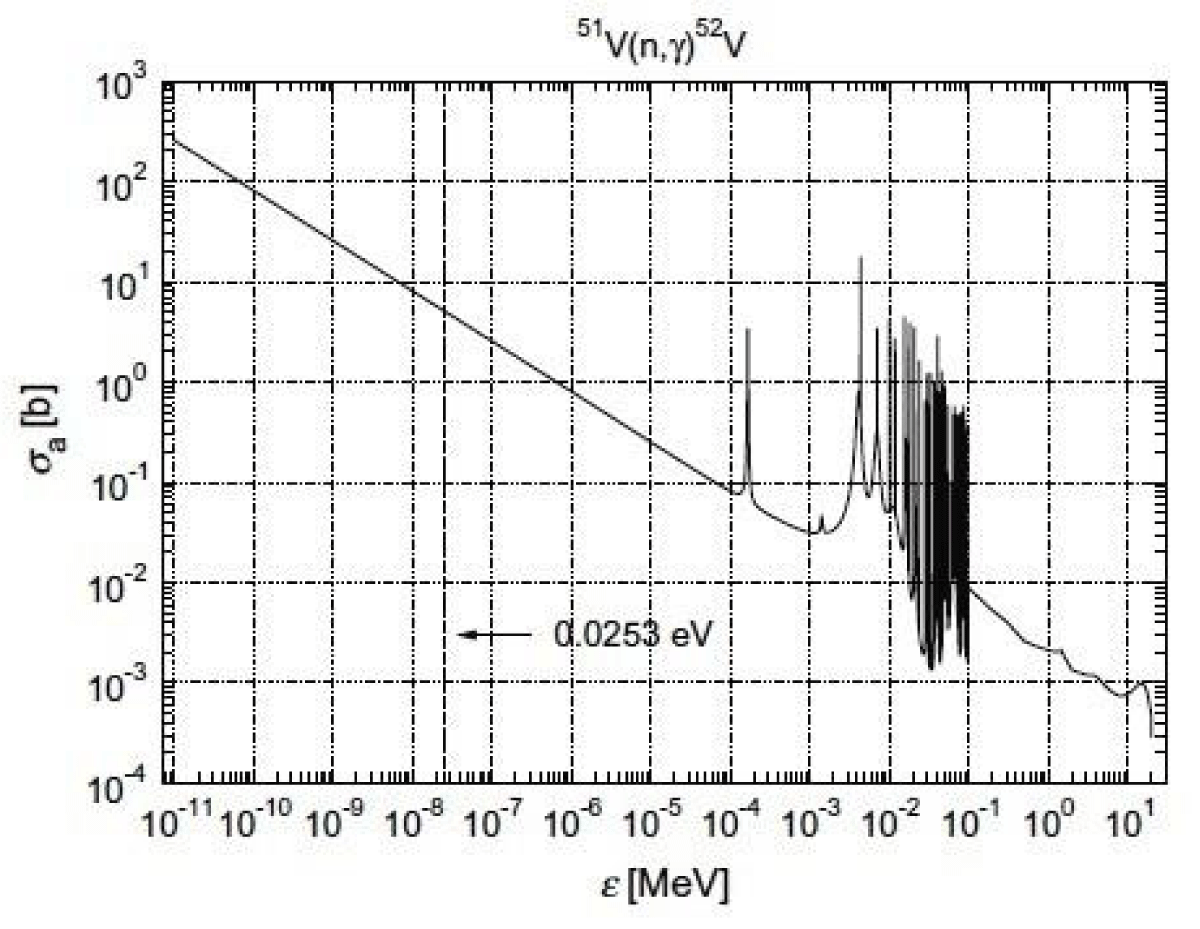
Figure 5: Absorption microscopic cross section for 51V as function of energy [4]. (Evaluated Nuclear Data Files, 2012).
The interaction cross-section varies with 1/v or 1/sqrt E. Due to this low interaction cross-section, the burnup rate of Vanadium SPND is low and is about 0.012% per month under an irradiation flux of about 1013 n/cm2/sec.
The major contribution for 99% of the signal is due to beta ray emission delayed by 3.76 minutes. 1% of the signal is prompt, which is due to parallel beta emission of maximum energy 2.6 MeV.
The Beta decay spectrum of the Vanadium emitter is shown in Figure 6 [6].
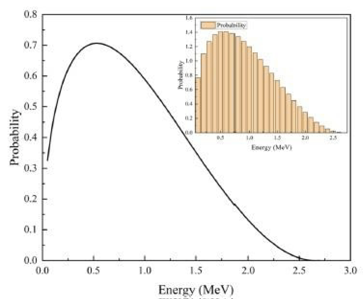
Figure 6: Beta decay Spectrum of Vanadium SPND [6].
Neutron sensitivity of vanadium emitter SPND comprises current due to 52V beta rays (Iβ) and 52V gamma rays (Iγ) [10]
The current signal from Vanadium SPND is given by
[10]
[10]
Where,
‘e’ is electron charge in Coulombs
‘V’ is the volume of the emitter in cubic cm
‘Rn’ is neutron capture rate per cm3 of emitter.
∈β (Emin) is the escape probability of beta rays from the emitter with energy Emin. to overcome the potential peak due to the space charge in the insulator.
are production and escape probabilities for Compton and photo-electrons
Rhodium emitter
The decay scheme of Rhodium is shown in Figure 7
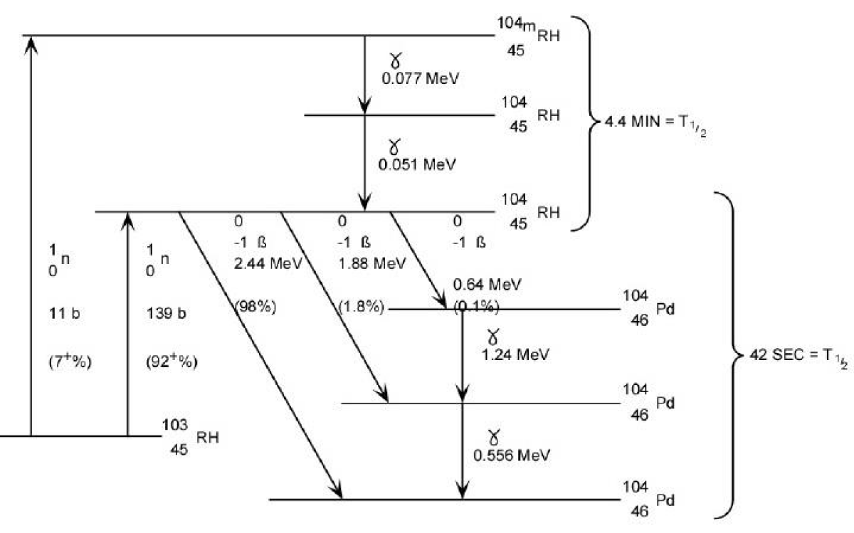
Figure 7: Interaction scheme of Rhodium emitter 92.3% of the produced signal by rhodium has a half-life of 42 s and 7.7% of the signal has a half-life of 4.4 min. The burn-up rate is 0.39% per month in a thermal neutron flux of 1013 n/cm2/sec.
The energy-dependent neutron cross-section is shown in Figure 8. It could be inferred that Rhodium has a good reaction cross-section in other neutron energies apart from thermal neutrons.
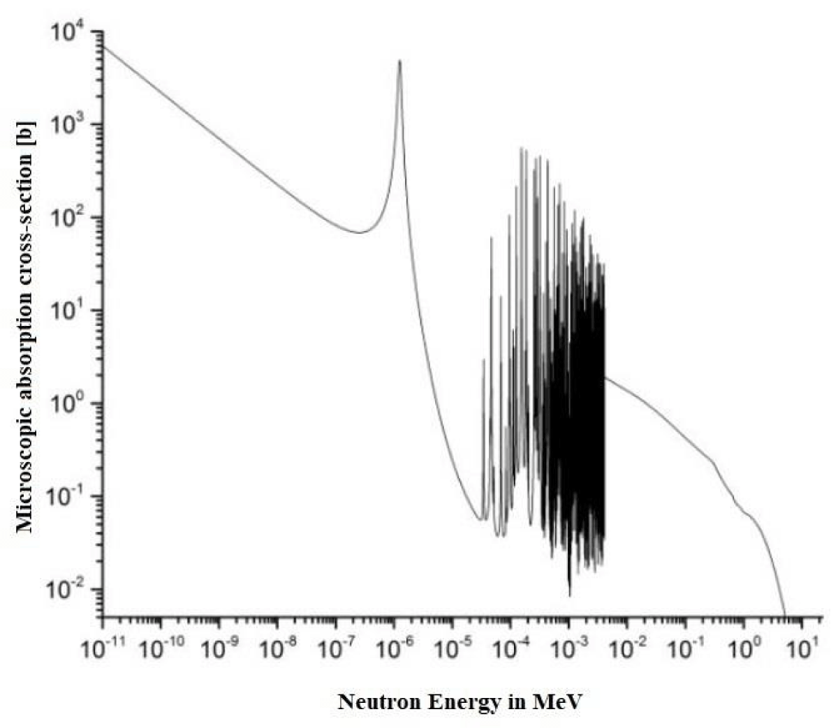
Figure 8: Microscopic neutron absorption cross-section vs Neutron energy for Rhodium-103 [11].
103Rh has a thermal neutron capture cross-section of about ~150 barns.
The current produced by Rhodium SPND is governed by the eqn [8]
(xii)
Where,
‘ε’ is electron charge
‘Pβ’ is the average beta escape probability
‘N’ is the average Rhodium number density
‘σ’ is Rhodium neutron capture cross-section
‘V’ is Volume of Rhodium
‘φ’ is Neutron flux in the Rhodium
The sensitivity of the new Rhodium detector is defined as [12]
[12]
Where,
S is the sensitivity of Rhodium SPND (A/nv-cm) and φ0 Is thermal neutron flux in the location of SPND.
‘I’ is the signal current from SPND due to thermal neutron flux.
‘q’ is the electron charge
‘L’ is the length of the Rhodium emitter rod
‘R’ is the diameter of the Rhodium emitter
∈(Eβ, r) is the escape probability of beta particles of energy Eβ Generated at radial position r, normalized by Rh emitter radius.
P(Eβ) is normalized beta energy distribution
σ Is thermal neutron absorption cross-section of Rhodium
NRh(r) is Rhodium atoms density at ‘r’
fn(r) is neutron flux at ‘r’
Cobalt emitter
59Co interacts with Neutron to produce 60*Co, which emits gamma rays to produce 60Co. 60Co undergoes beta decay with a half-life of 5.26 years to produce 60Ni. The isotope 60Co may also undergo neutron capture yielding 61Co, which finally decays into 61Ni with a half-life of 99 minutes. The decay scheme is shown in Figure 9.
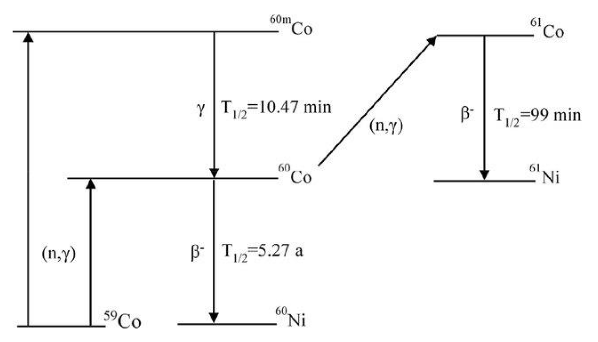
Figure 9: The interaction process between neutron and Cobalt SPND [13].
The output current of Cobalt SPND [14] is the sum of the prompt and delayed components of current and is given by
I(t) = Ip,tot(t) + Id(t) [14] (xiii)
Ip,tot(t) = Ip,g(t) + Ip,n(t) (xiv)
Ip,n(t) = K60N60(t) + K61N61(t) + ScF(t) and (xv)
Id(t) = I60(t) + I61(t) (xvi)
Where,
I60(t) is current in Cobalt SPND due to Beta decay of 60Co
I61(t) is current in Cobalt SPND due to Beta decay of 61Co
Id(t) is delayed current for Cobalt SPND
Ip,tot (t) is the total prompt current produced by Cobalt SPND
Ip,g(t) is current generated by Cobalt SPND due to external gamma flux
Ip,n(t) is current due to gamma rays produced internally in Cobalt SPND
K60 = 6.3147 x 10⁻³⁰ A.cm3; sensitivity constant for “concentration of 60Co”, atoms.cm-3
K61 = 1.7668 x 10⁻²⁴ A.cm3; sensitivity constant for “concentration of 61Co”, atoms.cm-3
Figure 10 shows the distribution of output current in Cobalt SPND with integrated neutron flux when it operates in 1013 nv neutron flux. As time elapses, the concentration of 60Co nuclei increases. The proportion of current, generated by 59Co decreases with the increase of integrated neutron flux, while that of 60Co and 61Co, increases with the increase of integrated neutron flux. It results in a higher and higher proportion of background current and delayed current appears with the increase of integrated neutron flux, leading to larger measurement error.
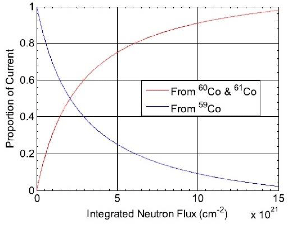
Figure 10: Proportion of output current from Cobalt SPND vs integrated neutron flux [13].
Inconel emitter
Inconel-600 is an alloy with 76% Ni, 15.5% Cr, and 8% Fe. Hence, the major constituent that contributes to the current is due to neutron interaction with Nickel. Table 1 shows the cross-sections and relative sensitivity for the constituents of Inconel-600.
| Table 1: The Cross-sections and relative sensitivity for the constituents of Inconel-600. | ||||
| Element | Atomic Number | Neutron capture cross-section (s) | Sensitivity relative to that for Inconel-600 | Principal Beta active daughter nuclei |
| Nickel | 28 | 4.43 b | 1.12 | 58Ni 59Ni |
| Iron | 26 | 2.55 b | 0.64 | 59Fe |
| Chromium | 24 | 3.1 b | 0.74 | 55Cr |
The current from the Inconel detector when put under neutron flux of ‘φ’ for time ‘t’ is given by [15]
(xvii)
(xviii)
where,
I0 is the initial current from the Inconel detector assembly
σ Is the effective neutron cross-section to describe the burnout of Inconel (~4.05 b)
σ58 is the neutron absorption cross-section for 58Ni (~4.6 b)
σ59 is the neutron absorption cross-section for 59Ni (~104 b)
N58(0) is the relative number of 58Ni nuclides per unit volume at initial time t=0.
It is evident from the above equation that the sensitivity is time-dependent on the cross-section of isotopes of Nickel. Nickel contributes majorly to Inconel emitter SPND current. The most abundant Nickel isotope is 58Ni which forms 68% of the natural element and has an absorption cross-section of 4.6 b. This isotope transmutes to 59Ni when it captures a neutron. 59Ni has a total neutron cross-section of 104b. Thus every nuclide of 58Ni which captures a neutron transmutes to 59Ni which has a much larger neutron capture cross-section, so that, initially, the detector sensitivity increases i.e. the detector breeds [15].
Silver emitter
Natural abundant silver consists of 51% 107Ag47 & 49% 109Ag47. Silver has (n,β) interaction. The interaction of these isotopes with neutrons leads to the formation of 108Ag47 & 110Ag47 which then decay by emitting beta particles majorly thus contributing to the current from SPND. Thermal neutron cross-sections for these interactions are 23.8 barns and 58.8 barns respectively. The decay chains for these isotopes are shown in the Figure 11.
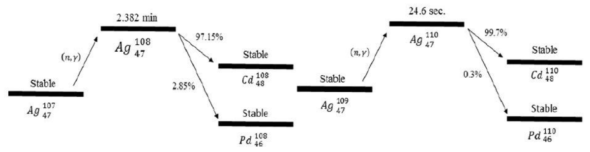
Figure 11: Decay chain of Silver [9].
The Silver SPNDs are usually used in steady state and slow transient measurements.
66% of the initial signal has a half-life of 24.6 sec and 25% of the signal has a life of 2.382 min. 9% of the signal is prompt. Silver SPND has average sensitivity, average burn-up rate, average perturbation of local power density, and a delayed signal [3].
Application of SPNDs
Reactor control and protection: SPNDs could provide continuous information about the Neutron Reactivity which is given as input to the control rods system to adjust reactivity for stable output of power.
Reactor safety: SPNDs provide information about the local neutron flux distribution within the core to identify abnormal conditions. Deviations in neutron flux patterns can indicate potential fuel assembly or core cooling issues, allowing operators to take appropriate corrective actions to maintain the safety of the reactor.
Flux mapping: SPNDs are used for 3D flux mapping in the reactor core for the reactor regulating system. They are used for estimating zone power and spatial power control.
The main significance of the paper is to highlight the characteristics of different SPNDs through an extensive literature review which will give insight into the selection of SPNDs for particular applications.
Different emitter materials produce daughter radio-nuclides with different properties that influence the characteristics of SPNDs like Response, Burn time, sensitivity, etc. SPNDs are classified based on the emitter material used.
Based on the literature review, a comparison between different types of SPNDs is summarized in Table 2.
| Table 2: Comparison of SPND Emitters [3,8,16,17]. | ||||||
| CHARACTERISTIC PARAMETER | ||||||
| Emitter Type | Nuclei | Type of interaction | Neutron cross-section | Response Type | Burn-up per month@ 1013nV | Application |
| Vanadium | 51V | (n,b) | 5 barn | Delayed, 3.76 min | 0.012% |
|
| Rhodium | 103Rh | (n,b) | 145 barn | Delayed, | 0.39% |
|
| Cobalt-59 | 60Co | (n,g,e) | 37 barn | Prompt | 0.094% |
|
| Silver | 107Ag47 109Ag47 |
(n,b) (n,b) |
23.8 barn 58.8 barn |
Delayed | 0.16% | Steady-state and slow transient measurements RBMK Flux mapping |
| Inconel600 | 58Ni 59Fe 55Cr |
(n,γ,e) | 4 barn | Prompt | 0.035% |
|
Prompt-type SPNDs like Co-60 and Platinum are used for applications demanding fast response like reactor control and protection at the cost of burn-up of material i.e. lower lifetime.
A cobalt detector has a response as fast as an Ionization chamber and is therefore preferred in reactor control and protection [17,18]
Delayed type SPNDs like Vanadium, Rhodium, Silver, etc., are used for flux mapping in reactors with high lifetime, because of high accuracy.
However, due to the delayed current component and the formation of other daughter nuclei in these types of SPNDs, they cannot be directly used for real-time neutron flux monitoring. To achieve real-time neutron flux monitoring, complex algorithms are required [19].
Figure 12 shows the comparison of the Cross-section between Rhodium and Vanadium.
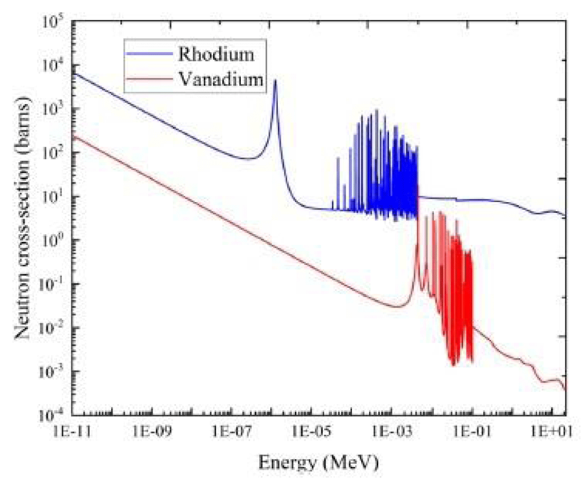
Figure 12: Neutron Absorption Cross-section of Vanadium and Rhodium [14].
Rhodium has a strong resonance peak in the neutron region having energy about 1.26 eV, where the neutron cross-section exceeds 4000 barns. Rhodium may act as a significant poison with neutron absorption only smaller than 135Xe and Samarium (149Sm). The sensitivity of Rhodium SPNDs depends not only on thermal neutrons but also on epithermal neutrons. Thus, the sensitivity uncertainty of Rhodium increases with time [20].
Due to the high reaction cross-section, the Rhodium emitter burns up fast. Figure 13 [14] compares the burn-up rate of Rhodium and Vanadium emitters.
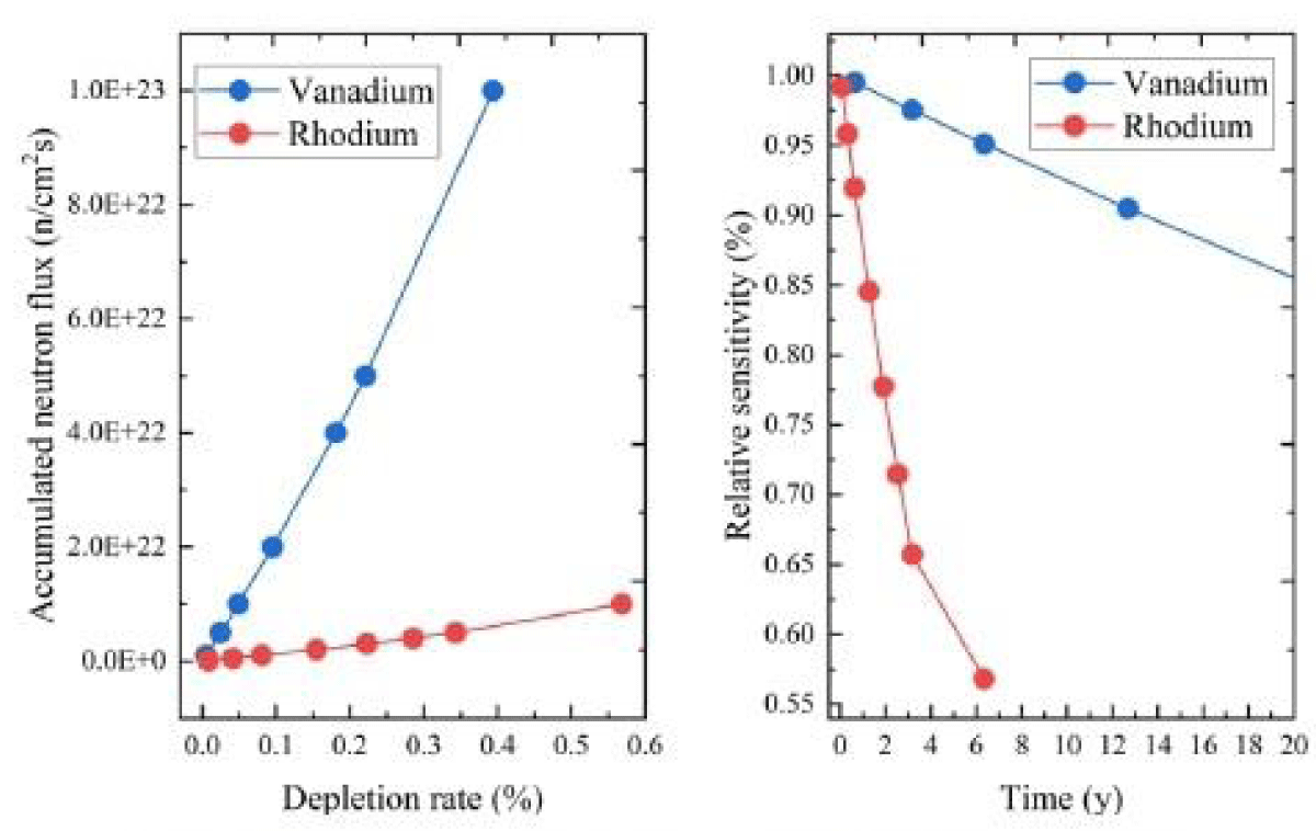
Figure 13: Comparison between Vanadium and Rhodium Burn-up [6].
If there is a step change in the power of the reactor, the Rhodium detector takes 210 sec for its output to reach 90% of the new equilibrium output. For vanadium, it takes 735 sec and in the case of Silver, it is 231 sec. For silver, it takes 11.9 min to reach 99% of its saturated value. Response to positive and negative step power change in the reactor is shown in Figure 14.
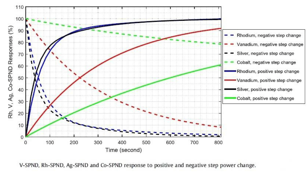
Figure 14: Response to positive and negative step power change in the reactor [9].
Some studies show improvement in the burn-up rate of Rhodium emitter by the addition of Iridium [21]
Cobalt SPND neutron sensitivity is badly affected with integrated neutron flux due to the build-up of Co-60 and thus needs correction to interpret the correct results.
In a neutron flux of ~1014 nV, the burn-up of the Inconel detector is expected to be 8% after 20 years. Thus with prompt response, low burn-up, longer life, and lower cost, Inconel SPND is a useful alternative to Co and Pt SPNDs [16]
The conductivity of SPNDs is dependent on temperature and radiation. The conductivity, for SPNDs, is generally independent of temperature below 100 ºC. Above 100 ºC, conductivity increases with an increase in temperature. The conductivity depends on radiation dose up to 300 ºCbut beyond this, it is dependent on temperature. The radiation-induced conductivity depends on the atomic number (Z) of the emitter and the conductivity increases with increasing Z [22].
The review has focussed on only 5 types of SPNDs. SPND emitters like platinum, Hafnium, and other SPNDs have not been reviewed and compared. Inconel emitter is an alloy and the data available about the interaction schemes of all the constituents are yet to be reviewed.
A detailed review of the literature was made on the SPNDs with an overview of general characteristics, types of emitters, their interaction modes, and characteristics. Comparison was made between Rhodium, Vanadium, Silver, Cobalt & Inconel SPNDs and presented in Table 2. Important comparisons are elaborated in the discussion section. For stable SPND operation, the balance shall be maintained between optimal emitter material and the neutron absorption efficiency in capture reactions [20].
- Ziebermayr J, Bock H. High-temperature incore tests of self powered neutron detectors. Atominstitut, Vienna, Austria; 1976:40. Available from: https://inis.iaea.org/search/search.aspx?orig_q=RN:40030715
- Ramirez G, David L. A study of self powered detectors for mixed neutron gamma radiation fields. Nucl Instrum Methods. 1970;85:279-283. Available from: https://doi.org/10.1016/0029-554X(70)90249-1
- Todt WH Sr. Characteristics of self-powered neutron detectors used in power reactors. Imaging and Sensing Technology Corporation; Horseheads, NY 14845, USA. Available from: https://www.oecd-nea.org/science/rsd/ic96/4-2.pdf
- Moreira O, Lescano H. Analysis of vanadium self powered neutron detector’s signal. Ann Nucl Energy. 2013;58:90-94. Available from: http://dx.doi.org/10.1016/j.anucene.2013.02.027
- Warren HD. Calculation model for self powered neutron detector. Nucl Sci Eng. 1972;48(3):331-342. Available from: https://doi.org/10.13182/NSE72-A22491
- Wu X, Cai L, Zhang X, Wu T, Jiang J. Study of neutron sensitivity for vanadium self powered neutron detector in nuclear reactors. AIP Adv. 2023;13:125015. Available from: https://doi.org/10.1063/5.0154279
- Goetz KC, Cetiner SM, Celik C, Hu J. Development of a fast-spectrum self-powered neutron detector for molten salt experiments in the versatile test reactor. EPJ Web Conf. 2021;253:05006. Available from: https://doi.org/10.1051/epjconf/202125305006
- Kim GG, Cho NZ. Investigation of the sensitivity depletion laws for rhodium self powered neutron detectors. J Korean Nucl Soc. 2001;33(2):121-131. Available from: https://koreascience.kr/article/JAKO200111921633949.pdf
- Khoshahval F, Park M, Shin HC, Zhang P, Lee DJ. Vanadium, rhodium, silver and cobalt self-powered neutron detector calculations by RAST-K v2.0. Ann Nucl Energy. 2018;111:644-659. Available from: https://doi.org/10.1016/j.anucene.2017.09.048
- Rao PS, Misra SC. Neutron sensitivity of vanadium self powered neutron detectors. Nucl Instrum Methods Phys Res A. 1986;253:57-60. Available from: https://doi.org/10.1016/0168-9002(86)91127-7
- Borysenko VI, Goranchuk VV, Piontkovskyi VuF. An investigation of models of rhodium emitter used in self powered neutron detector; 2022.
- Lee W, Cho G, Kim K, Kim HJ, Choi Y, Park MG, et al. A study on the sensitivity of self-powered neutron detectors (SPNDs). IEEE Trans Nucl Sci. 2001;48(4):1587-1591. Available from: https://doi.org/10.1109/23.958400
- Liu X, Wang Z, Zhang Q, Deng BJ, Niu Y. Current compensation for material consumption of cobalt self-powered neutron detector. Nucl Eng Technol. 2020;52:863-868. Available from: https://doi.org/10.1016/j.net.2019.09.010
- Razak RA, Bhushan M, Belur MN, Tiwari AP, Kelkar MG, Pramanik M. Clustering of self powered neutron detectors: combining prompt and slow dynamics. IEEE Trans Nucl Sci. 2014;61(6):3156-3162. Available from: https://www.ee.iitb.ac.in/~belur/pdfs/j14tns.pdf
- Allan CJ, McIntyre IL. Self powered neutron flux detector assembly. United States Patent. 4363970. Dec 14, 1982.
- Alex M, Ghodgaonkar MD. Development of an Inconel self-powered neutron detector for in-core reactor monitoring. Nucl Instrum Methods Phys Res A. 2007;574:127-132. Available from: https://ui.adsabs.harvard.edu/link_gateway/2007NIMPA.574..127A/doi:10.1016/j.nima.2007.01.084
- Strindehag O. Self-powered neutron and gamma detectors for in-core measurements. AE-440, UDC 539.1.074.8: 621.039.564. Aktiebolaget Atomenergi; Studsvik, Nykoping, Sweden; 1971. Available from: https://inis.iaea.org/collection/NCLCollectionStore/_Public/39/015/39015035.pdf
- Bock H, Stimler M, Strindehag O. Transient response of cobalt self powered neutron detectors. Nucl Instrum Methods. 1970;87:299-300. Available from: http://dx.doi.org/10.1016/0029-554X(70)90218-1
- Liu S, Shao Z, Sang Y, Cai Z, Chen H, Guo H, et al. A general method for delay compensation of self-powered neutron detectors in reactors. Ann Nucl Energy. 2023;193:110035. Available from: https://doi.org/10.1016/j.anucene.2023.110035
- Ulybkin A, Rybka A, Kovtun K, Kutny V, Voyevodin V, Pudov A, et al. Compton (prompt-response) neutron detectors: comparison of emitter materials through the nuclear transmutation model. Sensors Int. 2020;1:100020. Available from: https://doi.org/10.1016/j.sintl.2020.100020
- El Badry AM, Hassan SA. Sensitivity of developed self-powered neutron detector. 4th Conference on Nuclear and Particle Physics; 2003 Oct 11-15; Egypt. Available from: https://inis.iaea.org/collection/NCLCollectionStore/_Public/37/121/37121591.pdf
- Bock H. Temperature and radiation tests with Pt and rhodium self-powered neutron detectors. Nucl Instrum Methods. 1979;164:205-207. Available from: http://dx.doi.org/10.1016/0029-554X(79)90455-5